Showing posts with label Auto Performance. Show all posts

12 May 2013

Ian’s Short Ram Intake

I owe a lot of stories to the few of you who actually follow this blog, Matt’s Camaro has taken several leaps forward and a big step back. I’ve also done some work on other cars, and finally have my own project car. But to knock the rust off I will start with a little story that is still fresh in my mind. Ian is a young co-worker of mine, and has been seeking my mentorship in a great deal of auto performance knowledge for the past two years. A while back I helped him install a new exhaust system on a Honda CBR 600 bike of his (which I still owe a write-up on). Recently Ian got himself a nice sporty 2010 Mazdaspeed3 and now he wants it a little more sporty(fun) than stock.

He ordered two things to perk up his car a little. The first is a set of motor mount inserts. The second is a Stage Two Short Ram Intake (SRI). Both of these are from Corksport.com
 
DSCN2325
Totally stock 2010 Mazdaspeed3 engine bay.

DISCLAIMER: This is not instructions for installing these parts, more like a review of the install process. I have some corrections or amendments to the printed instructions that came with the new parts, and some tips to work in addition to the instructions.

DSCN2326

First we installed the motor mount inserts. These are pretty easy to do if you have a jack (that works with the car), jack stands, a 1/2” drive ratchet 17 & 19 mm sockets, and a torque wrench. I suppose you could do it with out the torque wrench, but I wouldn’t recommend it. I mention a jack that works with this car because it sits so low. My floor jack is a high-lift SUV style jack, and when fully depressed still needs about 8 inches of clearance to fit under the car. These Mazdaspeed3s have about 6 inches so we had to improvise a little. I would have simply used my ramps, but they are holding up the back end of a ‘66 Chevelle at the moment. In their place we used some scraps of 2x4. You can judge from the picture how long they were. They worked well enough. Instinct may tell you to screw or nail the boards together, but I have some logic against that practice. We only used the wood to get the car high-enough to get the jack under the front end. Since we were going to use the jack to lift it we would be taking the weight of the car off the front suspension. The suspension is located by an A-arm on each side (one for each wheel), which each move through an arc. Picture wingtips on a bird, as the wings go up and down the distance between the wingtips changes. As we lifted the car the distance between the tires became less, this caused the tires to move in and slide the blocks around a bit. If they had been nailed or screwed together they would have to tip, which could have caused binding and a more dangerous situation. To lift this car with a single floor jack place the jack under the middle of the K-member (named due to its shape). The K-member is a heavy piece of metal that connects the A-arms to the car and supports the back of the engine. Don’t lift on the plastic-work or the bottom of the engine/transmission. If your jack has a metal saddle I recommend placing a 4'”-8” long chunk of 2x4 between the jack’s saddle and the part of the car you are lifting on. This helps save the paint on steel parts and prevents cracking of cast aluminum or cast iron parts.

DSCN2327

After lifting the car we supported it with jack stands under the front sub-frame. If you need help locating this take a look at your owners manual for jack placement when changing a flat tire, from there look just inboard and you will see a build-up of structural metal with a few holes that convey its thickness. Once the weight of the car was on the jack stands and high-enough to crawl under it we moved the jack to the lowest part of the transmission, and lifted an eighth to a quarter of an inch. This is to support the engine while we remove the lower – rear motor mount.

DSCN2328

The three bolts on the aluminum (gray) motor mount. Are labeled 17mm in the instructions, however the car we were working on used 19mm socket to pull those. The two bolts going through the black steel portion of the motor mount are a different style but are very similar, and could be swapped if not careful, take the time to pay attention to the differences. Also while you are down there you may notice a small rectangular box stamped into the bottom of your K-member with the word “FoMoCo” on it. This stands for Ford Motor Company – You’re welcome!

The motor mount comes out pretty easy and the inserts are even easier. At this point the hardest part was getting the car up on the jack stands. Follow the pictures to see how the inserts go in.


DSCN2329DSCN2330DSCN2331

After the inserts are pressed in re-install the mount and its bolts and torque everything to 70 Ft-Lbs. Lower the car back to the ground and take it for a test drive, your car will feel surprisingly different.
Next is the install of the Corksport Sort Ram Intake. This was a little more difficult but with the right tools isn’t too bad. We took our time and had it done in about four hours. One word of caution about the Corksport intake –you may have heard of “cold air intakes” well this is a hot air intake. The factory air-box is sealed from underhood air, in fact, the air filter is fed air from a duct coming from a ram air scoop behind the grill opening. Ian and I took some measurements before and after using a Scantron OBD2 code reader. In the morning before we started the outside temp (indicated by the car’s sensor) was 68 degrees. While driving at 70 mph the Intake Air Temp (IAT) matched the outside air temp. When parked idling for one minute the IAT rose six degrees above the outside temp. After installing this SRI we did notice better throttle response and quicker turbo spooling, however at 70 mph the IAT was 3-4 degrees higher than the outside temp. and rose to six degrees above outside temp. in a mater of a few seconds. We didn’t even bother waiting a full minute.

What this means is this SRI can increase power while the car has air flowing over it, but if you spend lots of time at red lights you are increasing your IAT. Ian will be investing in a heat shield box or the Corksport stage 3 cold air intake in the future.

The turbo inlet pipe is well designed, but the quality of execution was 9.5/10. I noticed some welding slag on the inside, some of which you could almost scrape off with your finger nail. I used a long, straight-tipped screw driver to knock out what I could. It was actually kind of surprising how much I got out.

DSCN2334
This angle shows a few little chunks of welding slag that I knocked out with a long screwdriver. These are small pieces of metal that could get sucked through your turbocharger.
DSCN2337
This shows some of the crud that I scraped out of the inlet pipe.
DSCN2336

The instructions for this job were pretty good, and although we didn’t use them they have links to YouTube videos of the more difficult steps to help you if you’re stuck. The only exceptions here were some hose clamps that had to be turned to give us a little more clearance for the turbo inlet pipe and just a reminder, the grommet that you need to transfer from the old pipe to the new one includes a small metal sleeve/washer piece that may be stuck on the stud on the side of the engine. Be sure to get that into the rubber grommet before trying to install the pipe. Also we took the time to un-bolt a bracket under the battery tray that anchored the wire-harness that led to the ECU (computer). This allowed us to move the harness back and forth with out bending the bracket all to heck. Follow the instructions until you get to the point of tightening the 2”-2.5” coupler to the turbo. By the way. This is low pressure plumbing. Tightening the t-bolt clamps enough to see them slightly compress the silicone couplers should be adequate. Lastly the snap to connect fitting for the valve cover breather hose can be a finicky one, and you can make a tool out of a paperclip like the instructions suggested, or you can go to the auto parts store and get a set of fuel line quick connector tools. I think it was 5/8” or 3/4” that did the trick. Up to you if you want to spend a few bucks on them. I would recommend it if you spend much time spinning wrenches.

DSCN2332
Ian had a pro shop instal a big stereo system into his car. They connected the positive cable for the amp to the bolt that is to only be used for clamping the connector to the battery terminal. We relocated the power wire to the terminal with the black/red wire, next to the white wire. We also did a better job of routing the power wire out the bottom of the battery box.
DSCN2333DSCN2338

Lots of reviews and forums mention how difficult it was to tighten the T-bolt clamp on the intake of the turbocharger. I’ll tell you it’s very easy if you have a 24” extension on your 3/8 drive ratchet. Which can reach down between the firewall and the engine. I strongly recommend getting on even if it’s a cheapo from wal*mart. These stupid long extensions have really earned their keep with exhaust and transmission work lately.

The Boost Control Solenoid’s tube seemed a little loose on the brass fitting of the turbo inlet pipe. We used one medium sized zip-tie to clamp it down a bit. Again this is low pressure plumbing and often has vacuum on it. Nothing needs to be super tight on this section of the intake.

I found another situation with the “air straightener” on the new MAF housing. In general the build quality of the MAF housing body is great. What I didn’t like is the little bit of flashing on the middle of the vanes of the plastic “air straightener” its self. It was a simple fix with a file (an emery board could be used as well). It may not have caused any problem, but if I’m here, I fix what’s wrong. Also I recommend getting a can of “Mass Air Flow sensor” cleaner. Yes, this is specific stuff, you can not use water, WD-40, alcohol, or brake cleaner for cleaning the sensor, but it is worth it in the mileage and drive-ability to buy the can, I can promise that. And you can use the MAF sensor cleaner on other things such as other sensors and more rugged electronics through out your car (connectors, light sockets, etc.)

DSCN2339DSCN2340
DSCN2341

The duct that led to the factory air box pulls out of the car easily. And I wanted to keep it, yet in stock form it turned down and missed the new air filter. I hacked the turn-down off with a hacksaw and smoothed the edge with some sandpaper. Finally I zip-tied it to a small tube running along the top of the radiator just to help hold it in place.

DSCN2342
DSCN2343
DSCN2346
DSCN2345
Ian's car with a Stage 2 short ram intake and an upgraded motor mount.


23 December 2012

"Its been a while..."

Just as this blog was starting to pick up steam I went on hiatus. -Sorry for that. Here are some snap shots of the stories I owe you:

Replaced the muffler on Ian's Honda CBR 600.
Installing brake lines and CPP Master Cylinder in Matt's Camaro.
Getting Matt's Camaro back on the road.
Replacing the roof on Project Identity Crisis.
My tour of a Mopar Haven in Missouri.
As you can see I have been busy! To top it all off my server has kicked the bucket. Something about a guy in an American Flag Speedo disagreed with it...


I will split my time between fixing the server and writing about the stories I owe you. Look for things to start picking back up after the holidays!

Very respectfully,
-JimmyJam

26 September 2012

The LEGO Tire Test

   Many don't realize it. But the LEGO group produces more tires than any other manufacturer in the world. In fact in 2011 LEGO made 381 million tires. The next closest competitor was Bridgestone with a mere 190 million tires. The down side of this is the monopoly LEGO has in the LEGO car model world, where as real cars have lots of manufactures competing for sales. This means real tire makers have to provide proof that their product is superior. However I have noticed a major lack of performance data for any or the LEGO tires. Philo has done some comparative traction tests. And lots of people have published weights and measurements. But beyond that how do the tires affect the performance of LEGO Technic and Mindstorms models?

A selection of tires I will use for these tests. I haven't yet tested the tracks yet. There are many questions to be answered about the tires first.


   Granted there aren't too many people racing their creations on the ragged edge. There are some folks out there that build with function and practicality in mind. So I will delve into a multi part examination of how a selection of LEGO tires which are popular with powered creations can impact how they behave.

   Many times in my life I have heard that big tires hurt your mileage (MPG or Liters/100Km), and that better economy can be had with small skinny tires. However most people don’t think about why this is.


            -How does rolling resistance play in to this?
            -Don’t tall bicycle tires go over bumps easier than little roller skate tires?
            -What about tire and wheel weight? -A top can spin for a long time, usually heavier tops spin longer than light tops. Why doesn’t this hold true with tires on a car?

   There are some fairly obvious reasons why passenger cars aren’t driving around with tall tractor sized tires, but if diameter and mass can help a tire keep rolling over bumps why do people put small skinny tires on cars to improve mileage?

   It would be very expensive for me to test this with real tires, and the price of gasoline would almost be prohibitive. But I can scale it down with LEGO tires and electric motors. Although it is kind of embarrassing to consider the money I’ve invested into LEGO tires, the fact is I have them. And the energy needed to test these small tires comes pretty easily thanks to some rechargeable AA batteries. I also have a decent collection of different LEGO motors demonstrating a wide spectrum of speed and torque. So now I can compare different tire combinations with each of the motors and find the most efficient combination (as well as the least efficient).

   Philo did some excellent work analyzing most of the LEGO motors. He basically built a dynamometer, and used a power supply with variable voltage to examine how all of these motors perform at various voltage levels. From his research we know maximum speed, maximum torque, and each motor’s ability to turn electrical power in to power to move things. If you are familiar with performance cars or hot rodding you may be familiar with Engine Dynamometers. These are great tools to calculate how good a motor or engine is at producing power (and in the case of internal combustion engines; tunning them to perfection). But what you often don’t see on these is how parasitic drag from things like transmissions, alternators, power-steering pumps, radiator fans, and air conditioning pumps as well as driveline and axle losses affect these engines (which often need more tuning to make them drivable in the real world). All of this is done on something called a chassis dynamometer. A chassis dyno has rollers under the car’s drive tires which are equipped with sensors and wired to a computer which can translate torque and speed in to horsepower (the equation is HP = FtLbs x RPM / 5252 if you’re wondering).

   I didn’t build a LEGO sized chassis dyno (although that could be possible…) But I can do the next best thing – build a drag strip! When it comes to motors (or engines), power is a product of torque and speed. If you know how much a vehicle weighs, and you know how quickly it can accelerate for a set distance you can calculate the average power. If you break this distance down you can refine the data to see how much power the motor is producing at a given speed. The mix of LEGO motors I have demonstrate a varying range of speed (RPM) and torque. Some motors turn slow with lots of torque, some turn fast with little torque. I want to see how optimizing things like gearing, tire/wheel selection, and chassis setup can maximize power put to the ground. In most cases we are limited to 9 volts with LEGO motors (7.2 if using NiMH or 7.4 with LiPo rechargeable). So the best way to maximize power to the ground is to maximize how efficiently we use those few volts in LEGO models. That is what leads me to this battery of tests (pardon the pun). And to start off I need to know which tires are best for this and how to best gear each motor to work with these tires, this leads me to my first test.

   There are lots of ways to approach this test. Mine is to find the steady state power consumption of driving a simple LEGO vehicle with different tires and motors. I originally planned on making a 10 meter long track. But I didn’t want to work outside. I also didn’t want to drag all of my stuff to a gymnasium and explain what I was doing to every random person that stopped by. Luck would have it that I have enough room in my house to set up a 3 meter track. Thanks to the benefit of averages, I could simply run each combination down this track say three times for a total effective length of 9 meters (pretty close to my original plan) and still get a good chunk of data. Now I have five different motors, and 17 different types of tires for this test. That results in 85 different motor/tire combinations, then I ran each test three times that’s 255 runs. Each run was three meters, so I drove my little LEGO vehicle 765 meters! That’s about 0.48 miles, which isn’t far to walk or drive, but is a long way to chase a little LEGO vehicle for sure.

   The motors I’m using are from fastest to slowest (in terms of output shaft RPM) are:

5292 RC Buggy Motor

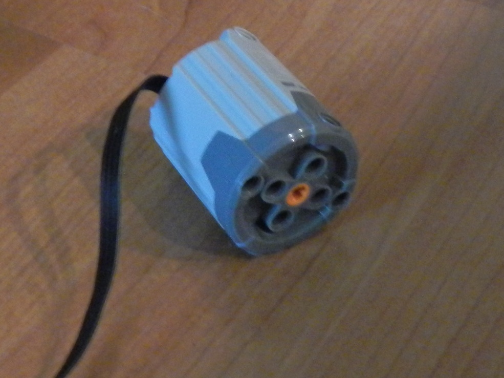
9670-1 PF E Motor (from the LEGO Education “Energy Meter” set.)

8883-1 PF M Motor 

PF L Motor (new with the LEGO Rock Crawler)

8882-1 PF XL Motor


The tires are:

Part # Style Size Mass Inertia
2696 Street 13x24 14g 1.391
2857 Balloon 20x30 19g 1.753
44309 Street 43.2x22 ZR 15g 1.424
6579 Balloon 43.2x28 S 17g 1.486
55976 Balloon 56x26 17g 1.851
41897 Street 56x28 ZR 24g 2.192
32019 Street 62.4X20 S 33g 2.775
61480 Balloon 68.7x34 30g 3.136
41893 dull 68.8x36 Hd 36g 3.425
41893 shine 68.8x36 Hs 36g 3.478
44777 PLASTIC 68.8X36 ZRp 18g 2.711
44771 Street 68.8X36 ZR 39g 3.612
2902 Balloon 81.6x15 29g 3.714
45982 Balloon 81.6x38 R 40g 4.288
92912 Street 94.3x38 R 68g 6.207
54120 Balloon 94.8x44 R 58g 5.833
51380 Lg MtrCyc Ft 36g 4.656


Mass of each tire was measured on a simple kitchen scale, I’m sure there is some error here, hence I didn’t bother with decimals. The inertia was determined with a weight drop test. In this test I made a simple setup that I could place on a counter and hold a LEGO axle a little more than one meter above the floor. I then filled a medicine bottle with ballast to make a 100 gram weight. I tied this weight on to a string and wrapped it around the LEGO axle, being careful to not let the string double over its self (just one long wrap). I then placed each wheel on the axle one by one and timed how long it took for the weight to drop to the floor. This was done with a stop watch and is not super accurate but does serve to demonstrate how the larger wheels are harder to accelerate than smaller wheels. This would apply to real world mileage if you did a lot of stop-and-go driving. I may perform a test later to see how much energy it takes to accelerate each tire up to a given RPM.

Armed with this inertia data I decided to keep first test slow, literally. I chose a gear ratio that was simple (for the sake of consistency) but also was a decent compromise for the performance of all of the motors. My three big concerns were: not going so fast with the RC motor as to spin the tires; not to bog the soft hitting PF E motor; and not to take a whole day with the strong, but slow PF XL motor. I found a 27:1 ratio easy to build and a happy medium for all of the motors. With the RC motor and the largest diameter tires the vehicle covered the three meter track in about 12 seconds, with the PF-XL motor and the smallest tires it took a little over two minutes and thirty seconds!

This test was very time intensive, but necessary to pave the way for follow on tests. With this test I was able to see how rolling resistance of each of the tires impacted the efficiency of the test vehicle. Below are videos of two of the runs I did, the only difference between the two is the motor used. The first video is with the RC Buggy Motor (fastest of the group), the second is with the PF XL Motor (slowest of the group). The difference in speed is very obvious.


Lets take a closer look at the tires:

2696 - 13 x 24
 2696 is a solid rubber tire made for "Model Team" vehicles and saw some use in several of the Technic Universal building sets as well. It is a hard compound and can hold a lot of weight. It is the lightest tire in the test and has the lowest moment of inertia (MoI).


2857 - 20 x 30
 2857 Is also an older tire, and is also solid. It is a softer compound than 2696 and had larger voids between the tread. the wheel is a smooth cylinder and can slide out or spin inside of the tire.


44309 - 43.2 x 22 ZR
 44309 is one of the smaller semi-pneumatic (s.p.) tires, and is what you will find in an NXT 2.0 set. The wheel is shared with the 55976 tire and can be used with rubber tread (caterpillar tracks). It's the lightest s.p. tire in the test and has very low moment of inertia (MoI).


6579 - 43.2 x 28 S
 6579 Is an old balloon tire. I think the four I have are from a 2000 or 2001 set.


55976 - 56 x 26
 55976 is a very common tire and is also found in the NXT 1.0 sets.


41897 - 56 x 28 ZR
41897 has the same diameter as 55976 but the larger wheel moves the mass closer to the outer edge, this tire has slightly more weight and MoI than 55976


32019 - 62.4 x 20 S
 32019 is often used for it's realistic look and heavy load capacity. The wheel has two circumferential ribs that act to stabilize the tall sidewalls. The wheel and tire have a lot of mass for their size, but the MoI is still less than the larger diameter tires.


61480 - 68.7 x 34
 61480 is very common due to Technic's push for tractors and construction equipment a few years ago. It uses the familiar staggered void tread pattern but seems to have fairly high rolling resistance compared to other tire near it's size.


41893 - 68.8 x 36 H
41893 Dull and Shiny - I have two sets of these wheels. The dull rubber ones (pictures with gray wheels) came with my RC buggy and were made for play outside. I'm not sure where I got the shiny ones, but it has the more common tire compound. The difference in weight was negligible. The dull tires had slight but consistently lower MoI. I haven't compared the traction values of these tires yet.

 In a strange way the slower motors seemed to prefer the shiny version, while the faster motors moved more efficiently with the dull tires. I hope to spend some more time comparing these two.


44771 - 68.8 x 36 ZR & 44777 - 68.8 x 36 ZR Hard Plastic Tire
44771 and 44777 are the same diameter, and made to look similar. While 44771 is a typical s.p. tire, 44777 is a simple and light plastic one-piece tire and wheel. The later is intended for "stunt driving" with remote controlled models.


44777 is only 18 grams compared to 44771's 36 grams, and the MoI reflects this by being almost 30% lower. However the slippery, non-conforming nature of the plastic stunt wheel makes it slightly harder to roll, as reflected in the Joules per meter charts.


2902 - 81.6 x 15
 2902 Made for motorcycle style creations, it is a large diameter soft compound tire with a narrow section width. Like 32019 the wheel has several circumferential ribs to stabilize the tire with heavy loads. The narrow width keeps the mass down relative to other large diameter tires, however the design (specifically those ribs) give it a pretty high MoI.


45982 - 81.6 x 38 R
 45982 Getting in to the larger tires, this one is common with larger Technic creations. It is a tall profile tire (relatively tall sidewall compared to wheel diameter) and is soft. It seems to give under load easier than almost any of the other tires in the test. It uses the same wheel as the 41897 & 41893 tires. It is one gram lighter than the 44771 but has higher MoI due to it's larger diameter.


92912 - 94.3 x 38 R
92912 Was created for the LEGO Unimog and is the heaviest tire in this group. It's tread patter is similar to 32019's, simply made larger. This tire shares the same wheel as the 44771 and 54120. It has the highest MoI, even though it's diameter and width are less than 54120. It is a very sturdy tire and appears to hold more weight than any other s.p. tire in the group. It may be well suited for a heavy creation but takes the most power to accelerate.


54120 - 94.8 x 44 R
54120 Is the overall largest tire in the group even though it is 10 grams lighter than 92912 (58 grams vs 68 grams) as expected it's MoI is high, but its large diameter lends it well to creations that need to cover a lot of ground. Although stopping and going consumes a lot of power.


51380 - "Tire Large Motorcycle Front"
51380 Matches 54120's 94.8 mm height yet has half of the mass of 92912. This was the tire I expected to have the greatest sustained speed efficiency of the group.


Here's some visual aides of how the tires and motors compared to each other.
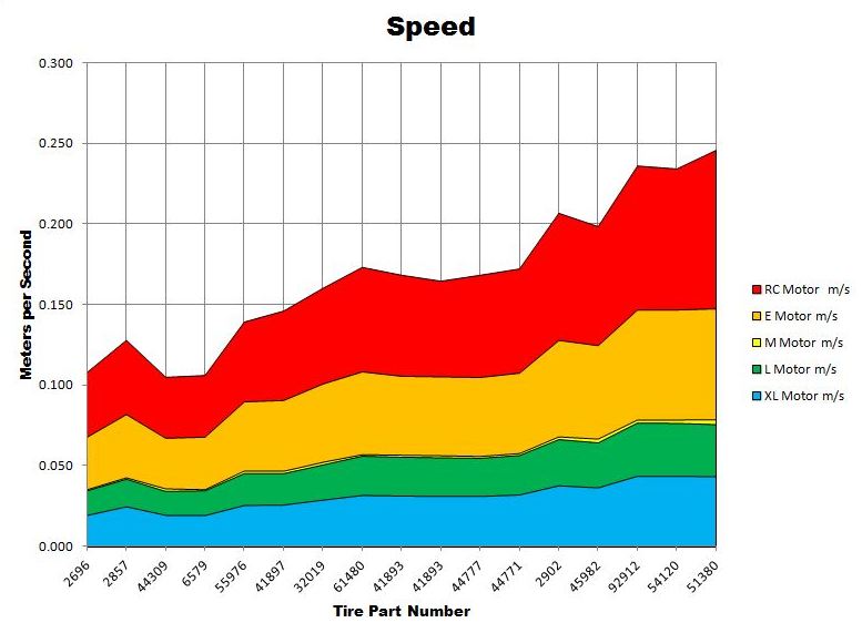
The first thing we will look at is the speed of the vehicle with each tire. Remember all motors and tires were run with the same 27:1 gear reduction. Philo recorded the no load shaft speed of the PF M and PF L motors to be very close (405rpm and 390 RPM respectively), this graph reflects that. Also of note is the difference between the PF E motor, and PF L motor. Again this graph shows that E motor is twice as fast as the L (780 rpm vs 390 rpm respectively). This graph doesn't demonstrate any one tire as better than the other, it merely serves to demonstrate how changing tire diameter and nothing else will affect vehicle speed (not counting for impacts on acceleration or wind resistance). But I wanted you to see how motor speeds recorded by Philo are echoed in this test, however with very light loading on the motors their true potential is not yet displayed. Again this is just a slow baseline.

This graph is the most literal equivalence of miles per gallon (km/100L). A Joule in the terms of electricity is one watt for one second. Since the taller tires increased the vehicle speed the motors had to do less revolutions to cover the distance, thus improving economy. This data is from the same test runs as the graph above. Ideally what we want to find is a tire that minimizes the Joules used to travel a meter. The very slow gearing used for these tests favors the motors with higher shaft speed, and makes the torquey L and XL motors look like hogs (the truth is they had lots of mechanical power to spare and simply need faster gearing). In this first test the E motor looks like it sips Joules per meter compared to the other motors. One very interesting thing to take away from this graph is how the RC and M motors nearly matched each other perfectly. This is despite the fact that the RC motor is 2.5 times faster than the M motor. My prediction is this scenario is close to ideal for the RC motor, and the M has room for improvement with better matched gears.

The next set of charts display each motors rate of power consumption (Joules per Meter), with each combination of tires. A common thing I noticed through all of the test was how the power draw would usually drop slightly from the first test to the last test. My method of testing to put a set of tires on the vehicle then conduct three runs with each motor, the first run was the 13x24 tire with the RC motor. I ran this test three times, then turned the energy meter off while changing to the E motor. Again I would run the vehicle three times, then shut off the energy meter to change to the third motor and so on. I'm not yet sure why the economy improved, perhaps the motor turns easier with a little warming up. Or maybe the energy meter simply flows more watts when it's cold. My hypothesis leans towards the later possibility since the phenomenon was more pronounced on the more powerful motors. For each of these graphs the vertical bars display the average wattage of each motor/tire combinations during the three 3m test runs, and the purple bar is the average for each combination over the three runs. Lower numbers mean fewer Joules per second, the following info basically shows how much power the motor was consuming to turn the tires.

RC Motor specifics:
The RC motor has an almost wild and un-predictable personality, which is demonstrated by the variations in data show above. For my tests I followed Philo's lead and used the outermost output for testing. At first glance this data may appear to be useless. However when you group similar diameter tires and compare power used the individual tires ease of rolling starts to stand out. Take for example the 56x26 and 56X28 ZR tires. These are the 55976 and 41897 respectively. These two tires are the same diameter yet on this graph the later was using less power to turn. If you compare this to the speed graph for the RC motor you sill see that the vehicle traveled slightly faster with the 41897. Faster speed and less power means greater economy. Try comparing the last two tires in the same fashion

E Motor specifics:
The PF E motor had the overall lowest rate of power power consumption, and was pretty steady with a few exceptions. Notice the 20x30 (2857) and the 81.6x15 (2902), both have soft compounds and aggressive tread with deep voids which has a negative impact on economy. Again compare the last two tires. The 54120 and 51380 have the same overall diameter and produced similar speeds but the 51380 consumed less power to do so. 
M Motor
The PF M motor was pretty agnostic to tires with this gearing with two exceptions. I seemed to draw less power turning the 43.2x22 ZR (44309) and 56x26 (55976) both consumed less than .5 watts per second. Now compare how much faster the vehicle traveled with the 55976 tire; that is a step in the right direction.
L Motor
The PF L motor produced similar speeds to the PF M Motor, yet consumed nearly twice the power. Also this graph demonstrates more clearly the trend to use more power on initial runs then on following runs. This may be the motor I use to evaluate this phenomenon.

XL Motor
The PF XL motor averaged about 60-70% of the PF L Motor's speed with a similar reduction in power consumption. Philo noted just slightly higher efficiency out of the XL than from the L motor (45% vs 42% at 9 volts). Judging by the rate of power consumption the XL motor was operating at near "no load" speeds. Faster gearing will improve efficiency.
In summary this test collected data on how tire diameter can influence vehicle speed, and how each motor responded to the rolling resistance of each respective tire. The next bit of research I do will be more exploratory in nature. I will choose 44309 (43.2 x 22 ZR), 41893 (Shiny version of 68.8 x 36 H), and the 51380 (Large Motorcycle Front), as they seem to have favorable ratios of meters per second vs Joules per meter. For these next tests I will reuse the same 3m track and vehicle chassis. And I will work to develop optimized gearing for each motor, in a sustained speed scenario. As always feel free to leave a comment!