22 July 2012

Trying to decide what to do with a Cougar...

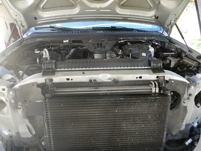
Today's post is about a project, but not so much of a work in progress, yet I'm still trying to solve a problem. The subject is a 1968 Mercury Cougar, which was purchased as a project car then had to be left behind. This first picture was taken around January of 2007 shortly after I took possession of the car; the second is current as of June 2012.

January 2007


June 2012


The car had a 302 that was bored .040” over. However the block still had some damaged cylinder walls. It’s hard to go much larger than this on a stock 302 so I found a new engine.
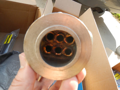
This pitting is a result of something called “washdown”…

The cross-hatch groves in the cylinder wall are meant to hold on to engine oil. This thin layer of oil protects the piston rings from welding to the cylinder walls.

When an engine is run overly rich the extra fuel entering the cylinder through the intake port washes the oil off of the cylinder wall. Since the lubricant is gone the rings start welding to the cylinder walls, the rings being a harder metal than the cast iron block pulls material away from the cylinder leaving a pitted surface. Usually this can be fixed by boring the engine block, unfortunately this engine has already been bored .040” larger than stock and is maxed out. Only two things could be done with this engine now. Either press cylinder sleeves in or junk it. Since this is a common 302 block it is cheaper to find a healthier block and try to get some money out of this as scrap metal.
I picked this engine up for $200. It was just rebuilt with cast pistons and was bored .030” over. The pistons from the old gray engine are forged +.040” Speed Pros. And although they were run in the old engine a bit –that engine was never really broke in. So those this block could be bored .040 over and the forged pistons installed.

This engine has some light rust on the sealing surfaces but can clean up easily.
The stock crank coated in grease and wrapped up.
Stock 302 rods with forged Speed Pro pistons. These pistons are .040" over sized
The crank bearing caps Speed Demon Carburetor and other small parts are all stashed in these storage bins.

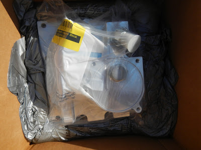
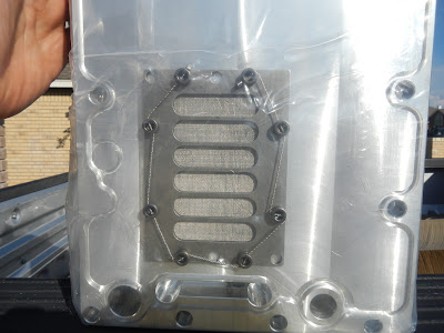
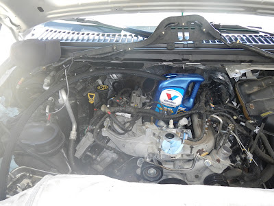
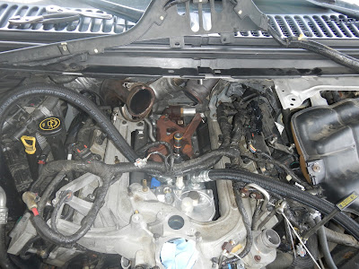
The blue engine was completely assembled and came with stock valve covers, Fox Body oil pan, etc.
I still have the 
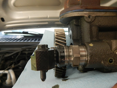
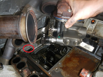
Cobra valve covers and V-belt pulleys that were on the Cougar. The blue engine came with serpentine pulleys (including a standard rotation water pump serpentine pulley), and an updated power steering pump.
Here's the old Edelbrock Performer 289 intake manifold.

And the still fresh looking ceramic coated headers.


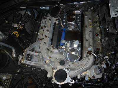
The blue engine also came with this Cobra/GT40 style EFI intake manifold.

The body is in overall good shape, while inspecting the wiring in the trunk I discovered that the rear fenders had been reskinned. It was an excellent job, the seam at the rear roof pillar is undetectable. The front fenders had some professional work done as well.

The body needs very minor work to make it good to go, mostly just bolt on parts that can be found in a catalog. The two most critical items are the left front fender and the rear valance. The fender would most likely get re-patched. the valance could be fixed very easily or just replaced, they cost about $125 new.

The fender was patched once before and could be re-patched or replaced just depends on price.

The rear valance go tweaked some where along the way. It doesn't have any significant rust damage so it could be repaired. Or simply replaced.
For as good of shape that the body is in the bottom side of the car is in bad shape. I don't have the full back ground on the car but it looks like it was up north somewhere. It basically needs a whole new bottom side to it; front to rear.

 Here are a few shots inside of the left front fender, not so pretty is it? There are few if any useable parts here and this is just one corner of the car.

The other side of the front is bad too. and there is evidence of work being done some time in the past in an attempt to repair some of this rust.

The worst part is the frame is shot too, and somebody tried to fix it before, the wrong way -twice!

This is the toeboard, aka the front side of the sheet metal under the pedals.

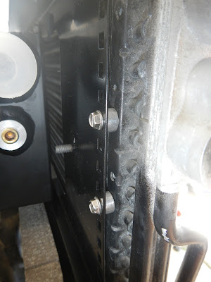
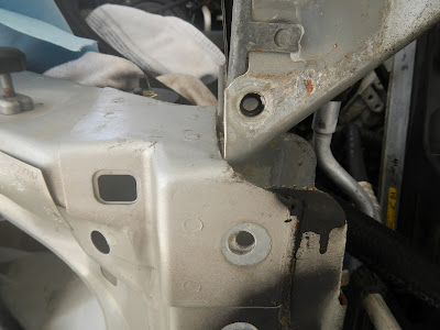
Notice the rust-through in the frame and the sheet metal behind the edge of the A-arm.

This is a picture of the left front frame rail as viewed from under the transmission. At the top you can see some over spray on the bottom side of a new floor board which was not installed properly. There should be no gap between the old and new floor boards, in fact to fix this right the remains of the old floorboard should have been removed completely. You should never cover rusty metal. Rust is a cancer and should be removed, replacing or patching rusty floor boards mandates that all rusty metal is completely removed and a patch that matches the area cut away get welded in. If welded in right you can grind the welds flat and hide the patch completely with paint. In the center of this picture is a tab for the park brake cable. notice the frame is notched around the tab -somebody capped the rusty frame rail.

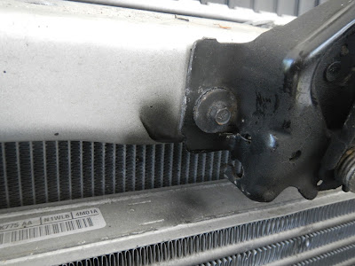
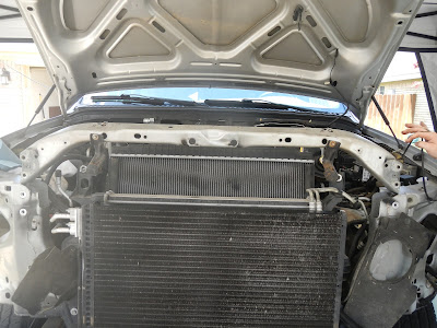
Here is the front edge of the frame cap and some of the rust that was left to eat away at the car. The top right corner of the picture shows the bottom side of the steering box. This is a critical part of the frame (which is pretty important already). When I saw this damage I immediately decided to remove the engine from the car. I was worried that moving the car at all with damaged frames like this could cause the car to buckle under the weight of the engine.


If you are trying to repair rust damage why leave rust in the car? Patch panels are just that not cover up the ugliness panels typically floor pans are made of several pieces of sheet metal that are welded together. For most cars that are popular with hot-rodders you can buy individual panels or complete floor pans. Often times the only part of the floor that is truly damaged are the low points and corners where moisture collects. In these cases you can buy and individual panel and go one of two routes to repair the rust. Either works fine, the first is to cut or drill out the original welds, and weld the entire new panel in. The second way is to cut out only the sections of the old floor, then use that piece to trace on the new panel so you are only replacing the rusty metal and leaving as much of the original metal behind as possible. Again either way is fine, but they each have pros and cons. The entire panel process takes longer to cut the old panel out, and there will be more welding to do. The small patch panel could be noticed by a judge if you are entering your car in a concurs restoration competition, but it's less cutting and welding.

Here is a properly patched floor (courtesy of www.oldcarsweekly.com). Notice they welded the patch in place of the original sheet metal, not over it.

Here is an underside shoot of the passenger side floor board of the Cougar. Notice the layers of sheet metal. Debris and moisture will get caught between the layers and cause more rust. This particular section could be saved; the patch panel could be lifted out, cut down to size and welded back in. However due to the amount of surface rust that is on these parts I would personally just replace everything.
Here is the top side of the same section of floor from the last picture, doesn't look bad with the exception of the lumpy tack welds. Consider this a word of caution when/if you ever take over someone's project car.
So by my tally it would take about two thousand dollars to get the structure of the car up to a safe condition. And that's before suspension, drive train, wiring, interior, and all of the other details that a car needs to get it down the road. I don't have much sentimental attachment to this car, it kind of fell into my lap. I do really like the look of this car and I could see myself in it. But the truth is this was someone else's dream car, and I would rather have an SVO Mustang. So here is my dilemma; Do I do the noble thing and return this car to the friend that was forced to leave it behind? Do I sell it as is to fund my SVO? Or do I restore it and sell it to make money for my SVO? I could keep the car indefinitely, but I will always want an SVO and can't justify having two toys. What are your thoughts?

04 July 2012

Fixing my truck part 2

Would it spoil the story to tell you the truck is running great now?

   It took quite a few weekends and lots of patience and research, but I found the problem, and a solution, as well as another solution to a few problems that hadn’t yet showed up on my truck yet. But since I was pretty deep into the engine there was no better time to put some upgrades in place that would ensure a long life to my Power Stroke. And I’m happy to say I am back to being a proud owner of a Power Stroke Super Duty again!

   I’ll begin with the fault that started all of this trouble: a failed Snap-To-Connect (STC) fitting. If you recall from my last post, the 6.0 (also the 7.3) Power Stroke engines use a unique High Pressure Oil (HPO) system to basically amplify fuel pressure from the 60 or so PSI coming from the fuel pump to the several thousands of PSI needed to make the diesel fuel injection process work properly. Compared to the low pressure oil pump, which is similar to the oil pump you would find on all car and truck engines, the HPO Pump is a relatively high pressure/low volume pump system. Hence any leaks in the HPO system will cause a very noticeable drop in pressure. The original design of the STC fitting is a real head-scratcher. Why would anyone make this small simple piece more complicated than it needs to be? (I’m sure my Dad would have a reason for that last part, he has plenty of “opinions” about Fords –Love you Dad!) At any rate there is a solution out there that fixes the common problem with a much simpler and robust solution, again SRMASTERTEC has a video about this. All of which reminds me of an engineering quote:

"A designer knows he has achieved perfection not when there is nothing left to add, but when there is nothing left to take away."
- Antoine de Saint-Exupry

https://blogger.googleusercontent.com/img/b/R29vZ2xl/AVvXsEiNTjZ2Eu2tUfcGr3q183SKSQKgdMCQ0gebH5hWt9XPfynEzxVhnYdJg4btW5cPdl2yeB7bFibX92EE02D2OaKaueF4hGFnNm_2KL1eD_UJ7wARcYvet6hWghGA_OawOJYRve9u4E7l7bU/s400/DSCN0701.JPG
This is the Snap-To-Connect fitting that I think is causing the problem. Notice the dark colored block on the left side is angled down slightly. 

https://blogger.googleusercontent.com/img/b/R29vZ2xl/AVvXsEgcu9R2sXAsJhaNjgcy7n9_MoIvTBROtBRGe2Es-V_aDWMntGfEZmPJU_rBo6dQLUTetUxk84vyfd2x_WyZGPVxNxKWpjN5tP4tmvnuRVXcOZg2ZBYbOiHFEu9jEdQwdX7qc5XlQzCRSiw/s400/DSCN0702.JPG
This angle shows how it has separated ever so slightly, the black rubber skirt should be overlapping the silver part much more.

https://blogger.googleusercontent.com/img/b/R29vZ2xl/AVvXsEi9hdHXMvJmREldGUPOUZZqwTCPw2WJZGCktHBQiEi6YXO3CoilmuWc_0aeDQBzbpoH9qO6Rln5VBO2pcxKNwyQXflDkUGa7Hi2OlVk0qztNjYeQctovZwiZv7Tj7aiBbaeV9WaShvVZgo/s400/DSCN0700.JPG
The wear marks on the rear engine cover (red circle) is a dead give-away that the STC has started to separate. In some small cases the STC can fail under very high pressure and actually crack the rear cover, which means the whole engine has to come out
https://blogger.googleusercontent.com/img/b/R29vZ2xl/AVvXsEhoW_fSufpeem6wNlRaHKz7t4vfHELrP0N3e2dSPogFOb24H4KzMluXYtIGAjELenBYrT3_x1HWRpqRb4He6bz8TdDJqBUzBCtcSU_x2gkvCEHCacqH7nOcDItAhrVrPMYpMQuG1227uFc/s400/DSCN0836.JPG
Old STC fitting on the left and new on the right, notice the difference in lengths, also how simple the new version is.
https://blogger.googleusercontent.com/img/b/R29vZ2xl/AVvXsEijkdoOFzyZvPD3AKtexO_9DzFpigH1NluRHT8ZvjmfrX7zF_e9q94l-fSqBqV8rbva_juFk72RobV80WChppNattTw2lKXMGprCNQS8UVsbBx8riQSf_Okar-Os4uUF6-FsLRsZKq5H2U/s400/DSCN0839.JPG
After I reinstalled the the HPO Pump it was clear to see the amount of gap you should have between the SCT fitting and the rear cover. Luckily for me this was the reason why my truck wouldn't start. There are more things I would like to upgrade in the future, but they will have to wait.
   After I got the HPO Pump out of the truck, it was obvious that my STC fitting was damaged. Although there are ways of verifying a failed fitting I was working in my driveway with a limited tool selection, and decided to work off of my hunch, so the search for a new STC fitting began.    During my searching I took a good look at the products offered by Bullet Proof Diesel and learned about a rather scary situation that can develop on the 6.0 Power Stroke, which is explained in good detail on their web site. In short the factory oil cooler uses engine coolant to control the tempurature of the engine's oil. This design packages well into the engine compartment and reduces the chance of external oil leaks but it has it's faults; it put more heat into the already burdened engine cooling system, the engine oil is always as hot or hotter than the coolant (not a best case scenario), and the small coolant passages in the cooler can become plugged which leads to expensive problems down the road. I considered buying their Fully Bullet Proof kit for a while then noticed they had the upgraded STC fitting included in their parts pack which they call the “Professional Install Kit” -I was sold, and ordered their kits right away. A few days later I came home to two large boxes loaded with parts and goodies.

https://blogger.googleusercontent.com/img/b/R29vZ2xl/AVvXsEiljAH3YrJHtUrnLEIphwuGDC36l3fbYlnT1Y0JR3dQN8FOXXiGoAJQJp-PO_9-vz8qVnZ3RkOVpfNHUdcx4SqMhVy61oHhVx8qdgDeOYGM8k2u5RI8jOwLq2cu_DO80skqyYCU0NLaUQU/s320/DSCN0761.JPG
This is what was waiting for me when I got home.
https://blogger.googleusercontent.com/img/b/R29vZ2xl/AVvXsEgze0B9eUNd5oyf9Ye-UoMs_XPCHKLmT8Ete_XjQZUx54hyLORKYRRLypRKiGLbPVDGW_7agymS2Cl0FFchz8Tv6RJ5fI-wFM75QleUvTaANf-4AfPc2PCaBo8ROtAGsGMVstjBBf8D96A/s320/DSCN0765.JPG
This is the heart of the Bullet Proof Diesel oil cooler kit. It’s machined from a single piece of billet aluminum and looks awesome, it’s a shame it is almost totally hidden once the engine is back together. I believe the name for it is “Oil Header”.
https://blogger.googleusercontent.com/img/b/R29vZ2xl/AVvXsEhM3cNEbAXZGG4hEVSSBIDLsOCcB5yGG0zX13fqI_uHPBUepBFgfegEiOON3zMCUdi9TuOcR0Cmj4LTRcycYxORW9RChi4m4UKjANQQuj_dFYzIpvQLvjzGzMqtq7P6q3ga8K7ZA_Kqkg4/s320/DSCN0772.JPG
Here is some of the swag that came with the kit, Nice cozy and also a bottle opener (hidden) the opener was black anodized aluminum and had an M1 Abrams tank etched into it.
https://blogger.googleusercontent.com/img/b/R29vZ2xl/AVvXsEhOinThsuWepKqVJuMYNMpxAH9g6gKnp_Mph5u8Jg26GxM5SUn_htgaPFwgPdpnhd-w-rwu73S71RvFTt9B9WVNLoD8xYCI4HTGY6sS5C5F-s1UhxvMMAgdcPZlsOyR1Pgmd8rcrJCYm2Q/s320/DSCN0774.JPG
Nice OEM quality chrome badge, My truck will wear this with pride!
https://blogger.googleusercontent.com/img/b/R29vZ2xl/AVvXsEgtOvRx66G3ZwAWugzLbfvD0SajnAxA9KXI5TylACRn1eH053SvinyzHDNIQVEmEqkGX3QGr6PDL92Iv7KUN4AHzhpt9b9tMLC9iRqWI2dKNhiDjNvPnkF6gVdx789iRccHiQeRDxqOmbU/s320/DSCN0773.JPG
Inlet end of the Bullet Proof EGR cooler, there have been quite a few articles on this already.
Inlet
end of the Bullet Proof EGR cooler, there have been quite a few articles on
this already.
https://blogger.googleusercontent.com/img/b/R29vZ2xl/AVvXsEgmd9buQ0vOe2In9dHC6LXpfd7kROYa0P77z71uPZnOWkwJ_HozI3p344vhTuhY7kHupJa0XPaKNFxKd6C4ST9MY9h6NRw-4fDFabS7weMbGn-zNlMvwtfjgW3F3V1JNaP6bnqpYOmWl94/s320/DSCN0779.JPG
The bottom side of the oil header features a very nice stainless steel mesh filter; this does the job of the junky nylon mesh filter in the HPO Pump’s oil reservoir.

   So after looking all of the new parts over it was time to begin the install. The instructions walk you through installing the oil header first, then doing the oil cooler and oil filter. Also in the instructions it mentions to have the A/C system purged/evacuated so that the A/C condenser can be removed. I didn’t have the equipment to perform A/C work like this, so I decided to work with the A/C system intact. The meant mounting the oil cooler to the A/C condenser while it was still installed in the truck. Well the Charge Air Cooler (CAC or intercooler for some folks) and radiator are stacked up right behind it. With the CAC tubes already out of the truck it’s pretty simple to remove the CAC its self. Happily I learned that if you drain about gallon from the cooling system you can remove the upper radiator hose, and with the radiator fan and shroud out of the truck you can tip the radiator back far enough to give you plenty of room to do this job. I’m sure removing the A/C condenser is faster, but keeping it in is cheaper, and can be done in your driveway.

https://blogger.googleusercontent.com/img/b/R29vZ2xl/AVvXsEhyMbOVDwqrAA9JXIOKG2gMIf3Fm33xrBjNooETjBLCqXsdIfcrpPikVT0oxMa-XfxiFzapaJr63xXIEj6m55NbPlXBj1MBrXLtJkPTbGFjVqqUELO1Tez9Z8FXDmgBRzcS0eFOQ8APqWs/s320/DSCN0781.JPG
Some people say to mark the hood latch location with masking tape, others say to use a sharp scribe, I choose a quick spray of paint. For one it’s hidden any way, and two it won’t get knocked off or cause rust.

https://blogger.googleusercontent.com/img/b/R29vZ2xl/AVvXsEiCzzPEAlcavByU09Y5GNpuxL3L6b6WQLoMqmJAG2Tk3g766t5RdmTSNtaAMvUJiYqnByGUSzkqfC5zzcRa1eEJetAyjEUQSJAJhkB_dl4r4ZlfUqc3usH0ALk2yAcNy0pEd0viXuvroV4/s320/DSCN0782.JPG
The instructions in my shop manual were a little misleading as far as removing the grill. It simply mentions removing the four screws at the top of the grill then squeezing the tab that holds the bottom. That may work on the ’04 and older models but the ’05-07 grills have five of these tabs which are very strong, good luck with them!
https://blogger.googleusercontent.com/img/b/R29vZ2xl/AVvXsEjF3psEVybOG4XiwE3YkEpcbRQ6-AQANYgOTLzjsYoouTsbj8iU9n-kTg2NsN77T2lZxxAmjOsjv3H86DNx6PXTkRk8punf2VNqpNgTdQIh2lIy2Cudx8uVZSlAE7RKfNuOEwoMZym8I_I/s320/DSCN0784.JPG
My solution was to take the whole front end off, the bumper has to pretty much come off anyway (which is really easy on Super Dutys). After removing each of the headlights which have four screws each there are eight fairly simple bolts to take the grill and headlight support off the front. Two each on the ends bolting to the front edges of the fenders, and four around the radiator opening, you can see in this picture how you can access the four middle ones through the grill. This proved to be very straight forward. Even though it took some persuading to separate the grill from the A/C condenser, it can be done. I recommend a helper when you go to pull this off, you should have had one help with the bumper anyway.
https://blogger.googleusercontent.com/img/b/R29vZ2xl/AVvXsEiMItD5He9JJHZkrWdfxx2Xw-ogji4lWyDoTBbvV4z-YKTF530PsRVFAbgB3_7TrldOXs-dYByOwbk9005yr84oe7E4zswBksjuXJAQpOiXkP1uImHiyUjAaZbeiFqna425w7eqoorz5wg/s320/DSCN0786.JPG
There you go, with the grill off and the radiator tilted back there is plenty of access to the A/C condenser.
https://blogger.googleusercontent.com/img/b/R29vZ2xl/AVvXsEgoRrO327rmjDPW4YIf8kLkJD16zskmgnk-J0OrYKpCdvXm88FhocJDIiMy0Q5wS-M9KcpS2D8VUyV17vs-vloXoxxkpoSlHsT1Sd8WWvHtJS_lCakPkbRTBQrzjf5JwVSh_C_IWNqNcZA/s320/DSCN0788.JPG
Now that the truck is ready for some new parts here is the pile I’m starting out with.
https://blogger.googleusercontent.com/img/b/R29vZ2xl/AVvXsEgDqlbxzyMIcvG9hSqzHbVSArm_dGwSveiM5hHnPXZPdBcTYBVSD33sirTKeNG4jqB9zGCIdDy9_azdOcU3JqJKtq7UHD1mAptkIvbHBAxEuxuRDsBmzntptfVA0M6P_LBRzO2ZU8bgEUs/s320/DSCN0790.JPG
Installing oil cooler on its bracket.

https://blogger.googleusercontent.com/img/b/R29vZ2xl/AVvXsEjykEMpI_V_oh_kOjE6xAzjS2Py0UqQQxlNg3R54uGnSl7_44GD2R9f5g4kY3IgTSgN3o9fRwf7ANQNoX0Um3-uSrJkhcuuOwCXsYKUG0iyxvbq2t_GEM_16_LG3-BhVIzbhNzY1XrGXZo/s320/DSCN0792.JPG
Some folks may not be familiar with these type of connectors, to install them properly you should first make sure the nut is turned back all the way like this. Then you can start threading the connector into place.

https://blogger.googleusercontent.com/img/b/R29vZ2xl/AVvXsEh3mBa-T9nujN0Na_1buGxKQ7J9kiJvSm5dqRtOD_MnhW8qAgpsC5dghtMfrFm8eVBWLyefaBEeafeWHfnraLqbfKOZXDbUPS8WRl1ozMU3ALGdaEurr1qggJRx6_cl-xv1fFvmeohXA6A/s320/DSCN0793.JPG
After you thread it in as far as it can go you back it off just enough to get the right angle on it. Then you tighten down the nut to squeeze the o-ring down to the sealing surface.

https://blogger.googleusercontent.com/img/b/R29vZ2xl/AVvXsEh91-Mkzfr3tdCDeCs1Ytcu2XITzhS2QW1CylfPXSXMgWJm1cD_jgEsoJxLKZUzls0b80MtVw-jECN1A53Ev7EetRtq41qjQfliiP2LbseG-L4yCZMT6K6uRacawcNyqbz7YDvNswaf1r4/s320/DSCN0794.JPG
After installing the fittings and the brass plug it was time to start mounting the oil cooler on to the A/C condenser. This was a fairly simple matter of finding holes that lined up while keeping the tops of the oil cooler bracket and the A/C condenser level with each other.

https://blogger.googleusercontent.com/img/b/R29vZ2xl/AVvXsEgnyoGGOaPOweiCLil6P86s9u8-ZjsIB6VISVZHJCubsci1-OWlxY8-CQpLcWGVov9nje0IixP2hQJp08-cyJKJbUyTqCCAI9QeIm28eZTBdJuLpb197UyuLQA3aIN7oZXbrME52AtCc70/s320/DSCN0795.JPG
This is how the screws lined up on my particular truck. There was no drilling involved on my ’05. If you’re A/C condenser does not have holes you may have to drill them yourself. Note the brass plug on the end tank of the oil cooler this will be used for a future modification.


https://blogger.googleusercontent.com/img/b/R29vZ2xl/AVvXsEgtVIwvXJFcnJQtlyZ2VPvQFl5blVuB1h0GM_5-dN_9w21gthfWhGAZTI6RteK6N7cbgE3a_x3OBACJh06kf0TQ55t8jZ2kUOUNugTdwUSgxI9jyRaL5eqR0Mr-FJ48S2wnbOyExn1jXD8/s320/DSCN0801.JPG
With the oil cooler done the next step was installing the oil filter block I bolted the block to the bracket as per the instruction, then added my own step of spraying the hardware with Rustoleum, notice all the rust my 37k mile truck already has.

https://blogger.googleusercontent.com/img/b/R29vZ2xl/AVvXsEgj9KPTcheWg3rUbHLY2xaWrVqh_xLTrBdmTMEHZBEzcL00ks3wlkiJ1dKV3R00PMWm9KeteUUyBJR4vF1nShyphenhyphennMLU6sDuN3lZPdIBMVisfd3qeVa2biDdJgoZ3yIh6NwRKzB32BHbeHkU/s320/DSCN0802.JPG
In this picture you can see the nice stenciling done to the top of the oil filter block. Notice there are two inlets and two outlets. The stenciling is a classy touch, but is not visible one everything is installed. And you can’t see the inlet and outlet labels from the bottom side.

https://blogger.googleusercontent.com/img/b/R29vZ2xl/AVvXsEiP_dCXOBzmP7NxlG_SH6t4jpdBD5wPiXH3uKN04Pprntzlouy_JVxYBlAtXaOCceWc7MsHo249BTo5KZqcYIYhmyEXfN9Yt5Cv_t0xy8sqhpsz7zsgrdbLkt_L9pm7ybFuIOWsa1T7ZLI/s320/DSCN0805.JPG
The extra inlet and outlet ports require plugs for a typical install. This requires a ******* huge hex key to tighten them. I didn’t want to make a run to the tool store to buy one, and didn’t want to pay for it if I did. So I raided my parts bins and found these nuts and bolts. Stuff like this is how I got the name JimmyJam.

https://blogger.googleusercontent.com/img/b/R29vZ2xl/AVvXsEhuVp1qLztgA2yCHzrI70Qlf3ElKqXKUQHcBojwDKFoGHOJcXO6QdrlKyPCqxdZeFGkApoGJL-5sdV5dkdrR1YhB62KKXe_JiIou2S45tM7anCd4T5vmMW3ZlG6lNT8uaw1-FTsKdllWO8/s320/DSCN0806.JPG
The JimmyJam hex key in action.


https://blogger.googleusercontent.com/img/b/R29vZ2xl/AVvXsEhUo_fYBOW-IlhtqH7I927l949Iqzb5A4IQca7fvneyav7bNTUaJ7vB6dCJv3tVKPCdwj17fa5ezXZRuxXY1N72U_-dLJSvXi0h0cjo5ls_b7q8gmoPPyaEBxIhhkMqmt_Opgt9YWyxfb8/s320/DSCN0807.JPG
Plugs installed, and no one would ever know the difference.
https://blogger.googleusercontent.com/img/b/R29vZ2xl/AVvXsEhVXn3RxY6OQh1VVc2KZYKf71ZgMOdysXSroNyYt1J19mVSHV0ocKH096MlvQWJjQ1MzPA2yBLxGxba5RqRo8kMfzE9VquHw6Qj2pIo4-JIRr7JKxzbBhpVWcdJMGY3k3S5g617be-lH60/s320/DSCN0809.JPG
The two slots on the right will be used for the oil filter bracket.
https://blogger.googleusercontent.com/img/b/R29vZ2xl/AVvXsEgQMjHW_hZTqQtcihJG8UWglBpf7ZxYB_5yoLNFbupy2XkqFM4ewMtQKInnvijMI4k49_hxlFj2hVC-E8U-ZbFUkpQFDC47Z44yNYlPx2xzfyRhxEisNx3v4Mc8jMa1rSDbs2c86bZt0jU/s320/DSCN0810.JPG
Before installing the oil filter I treated some of the rust with rust reformer. Germany was hard on my truck.

https://blogger.googleusercontent.com/img/b/R29vZ2xl/AVvXsEiFLucf-Q4oyxtBoCS9N4u3EyFl6-y2XdbHW-cYaQb3Dk0Y3TEI_zz-epZ5DIPWrsbDRZVp2-GOthHGkCn3QHcB5J29_4ND9kain46QGqBP5WxD3LGgwSH5hGqG-rVv4EaLwrUGQ6OXb6w/s320/DSCN0813.JPG
This is how the oil filter will mount to the bumper bracket; once the headlights are installed they will sit right above this.

   With the cooler and oil filter bracket installed the next step was to start routing all of the hoses. This meant I needed to start putting the front end back together on my truck. I didn’t notice while removing the radiator support that it was wider than the slots that support the ends of it. Since I will be back into this territory whenever the time comes to upgrade my Charge Air Cooler, I decided to spend some time correcting this to make the next trip easier.

https://blogger.googleusercontent.com/img/b/R29vZ2xl/AVvXsEjoT9b8KxPzNg_Z_zgrgVXtm5kE_ATHzaq752ViA2WVAJ-T0Q8kjf09p_426-kAjMPbzSBa4cgH9SznzqN1Fd23SkRw-XgCxN0XhAvgrC_ggGuEyGD2NXLa3oRtAN8ljMQvMD63058qCh4/s320/DSCN0817.JPG
Picture demonstrating the radiator support is too wide for its slots.


https://blogger.googleusercontent.com/img/b/R29vZ2xl/AVvXsEgkdRIMNPCuH-Zt-yrDaou9Tnq2Tgb6nU_0scFQ3vTlS0VaLu-ZD6e6hd9tTKKjtBcxASAqSNsOE6lpEbjahePRhrGf7jYx3AD2HmwQ_QyTnsM4dG396Omz7QuDDUPxAdxco53R34NoY_w/s320/DSCN0816.JPG
Problem


https://blogger.googleusercontent.com/img/b/R29vZ2xl/AVvXsEi6yJKY7bHOregVt9wNpYeVzQRvhRN8fEs-oOEFQ0OXY5ySizN4FY5IdqCvEXZ9Ipu8mG6kq1lr3uz7itpVeDvga9MTaj4joGROV96Bx8blRwKX5mW_jeHZG8LuYE9cH7myCOtUYfMxDdw/s320/DSCN0822.JPG
Problem solver –I’ve always believed the Milwaukee Sawzall was one of the greatest problem solvers known to man.


https://blogger.googleusercontent.com/img/b/R29vZ2xl/AVvXsEjsvMjVLYSgEfanTMAwEpxnda4JMljxndrzF_RavU63yfbCjMIA-Oq_AtIgdKI6p-sIpzvCiaGxt7Ye61YsaFPp-1Gi9uxx_EBAfL24rkL-dVS0_qLVUUsi-lSwlsCjz_L6XR2mr6oLiFY/s320/DSCN0821.JPG
After a quick touch with the sawzall. I had a slot that was wide enough, but it had some sharp edges.

https://blogger.googleusercontent.com/img/b/R29vZ2xl/AVvXsEhvqT3smG85tRYu6FfHQT9PWF39-Rc1RuxXveLLYiXmLv1aMGyFZ1x6oCFfRXqnHuhsIXFl2Dlh8iQGt0bRRPppjmfsaK_LO_Qss-9FMJSq4RU-J3oYgQoaNkNdk5fWTcTGnEYa8CBlr2w/s320/DSCN0819.JPG
JimmyJam’s Files, My wife made this sweet custom holder. Too bad this is the last time it was ever this clean.


https://blogger.googleusercontent.com/img/b/R29vZ2xl/AVvXsEixcgwkjcPalC7iS68frle0ry8E4y9VxC9LXlTK5WxbNODhTuSDa_Endyq8cgIlj2FsfvXs1NpfR0FSTvBsqyZrlCExDRcsrfwnk7kvHVk2xi5TUoiBuURTm1fYsxXomMIFAiHibkwoqdQ/s320/DSCN0825.JPG
All finished.


https://blogger.googleusercontent.com/img/b/R29vZ2xl/AVvXsEhVX0kp6Tovmm3XUWN1p0QXJ7RZB0lbxvACn4wmvRJ-rupRtS7nRp-qSj9r0FtivWq138Z928FJ6yxABgrfvrW7R65HZAuU-yOgskJ656Sbx7Nxzj-cqVwLt9lJEjVEK_wsiJVnHI8lLUk/s320/DSCN0833.JPG
With the front end reassembled it was time to start loosely following the instructions again. This meant it was time to put the oil filter on and start routing the hoses.

https://blogger.googleusercontent.com/img/b/R29vZ2xl/AVvXsEi7oxQXGJAqUdzlONuDADTYLr57JJCuGQsI84cmWzWfZNFHQoC80RABKRvKh9oNt1ONEv4vh55ZGuMg2sGlMnzLFpr3iE_dpRfQMnfnn5GK8gsysEnBHSDy2Ot8OSgRzdWguZdlIBUXIdo/s320/DSCN0848.JPG
Here’s the new spin on oil filter and the old cartridge style filter. Although the cartridge was simpler and probably much easier to manufacture it was always difficult to find compared to spin on filters. Also I never cared for the idea of swinging a dirty, oily cartridge over the front of my truck, nor  the idea of something falling into its reservoir. Secondly the spin on style give you a lot more brand choices. It’s worth noting that the spin on filter needs to be loaded with almost a quart of oil before you spin it on. Warning -it will get quite a bit heaver as you fill it don’t be surprised.


https://blogger.googleusercontent.com/img/b/R29vZ2xl/AVvXsEhrtFLk1uHDjg2PJQwS4zKufLa6exqzC6PCXTe9ZBlPvlWHfAFx7V4YPHXHnNCU9oj__pvp5GGw44Ois1YhyvEeIbyNU-I6z6Pi8hj69W11Cz1FmJv2hAg2AJHb4IAR5uf47aSc02uLTls/s320/DSCN0831.JPG
While putting the filter on I noticed the edge of the condenser rubbing on the hose between the filter and the cooler. I got my big pliers to make an adjustment.

https://blogger.googleusercontent.com/img/b/R29vZ2xl/AVvXsEjBh6-D7J-TAO4xNH0I9iF5qqY4zEq7eOQIsTt0mWifnHzBPo7eTy_rM7JCVnFmEHuZWnKg57ez61BI9oiHu2-fIpKzUygfl8BMZv9rWvHtY-Uz-vsSbMcL65Hiy6fq19j6JhUbqIOZrzo/s320/DSCN0832.JPG
The fit looks a little more comfortable now. I will need to check this in a week or two to see if there is any chafing going on.

https://blogger.googleusercontent.com/img/b/R29vZ2xl/AVvXsEg4b5xQcuYeAJQLabb3w7gdk3JIwZ2g3KEBo-BRrU-TUlI5bMaS9o06lgfLWpwsOQQsSJYlSG58YbPBkzek5LvqjQhIwYgYg5xIkqMxTV396i7eQjMfnq2Pm-EnaFis6Js3ajZw64dhn1Q/s320/DSCN0844.JPG
Installing the oil header was very straight forward and I quickly had intake bolted down and was ready to start running the hoses. A few notes. The blue silicone hose in the middle sits just right to make it a pain to install the turbo pedestal. Bullet Proof Diesel if you are reading this please check the fitment of the EGR tubing with the turbo pedestals. Also I recommend pouring a quart of fresh oil into the HPO Pump reservoir before installing the oil header. I ended up having to use a small funnel to fill it via the oil feed line port on the header –a slow and messy process.


https://blogger.googleusercontent.com/img/b/R29vZ2xl/AVvXsEjSd2lQXOVFfheM6AVoJ1eKd5aWxY6zRw65hgqMSbEf58UU8eTJwNo3lFFKA9cPtTRnARelL0xdTYv0xmEEABLM90lJihTpYJI1Bbfjl2j_h3VulTZSJNaB0UVT79xe3S7v0-40arpDc2k/s320/DSCN0843.JPG
Before proceeding too far take a look at the IAT2 (Intake Air Temp sensor #2, sensor #1 is in the air filter to turbo pipe) sensor in your intake, if it looks like this it needs a cleaning, I used a combo of brake cleaner, and MAF cleaner. Carb cleaner may work too.

https://blogger.googleusercontent.com/img/b/R29vZ2xl/AVvXsEiY9Tk_EcrlGLQFqc0KuqfUvNyKFbCF3KYBEppPySUbqpsPf5223XypgKhR302aMrbPNf_tTeqPWDd_CAm8a56HkvXeoFneULkzYw3VMF9Tw8tqp1wp3RK2nvz3B8CBCeA1hjH2MimsIiQ/s320/DSCN0668.JPG
I’ve showed you this picture before, it’s my dirty EGR valve. The soot that flows through this EGR system is how my IAT2 sensor got so dirty, I wish I could just delete this system, but I’m too responsible for that.

https://blogger.googleusercontent.com/img/b/R29vZ2xl/AVvXsEjt6Scq8zxp0hTjrZs5aY3rmgBKJgjrDDSTnK8eF3I0mwhUAG72vW-nIfMYe7lpuUcsbwenNsd57h3UCqTc-2VjCfQSjVaQC-yw_zIjm5W8QO6jT330ra98oMYGkbivOs0sO5VBr-1lHWY/s320/DSCN0865.JPG
After a quick blast of brake cleaner, and a rinse of MAF cleaner the inside of my EGR valve is cleaner than the part you can see once it’s installed.


https://blogger.googleusercontent.com/img/b/R29vZ2xl/AVvXsEipkuVopjFanVOM81raQWSEne4uElrImEpAZCfUOFPrclXHST0tZjYqR_zRt_gkNqdjwarwKG6oeeccSCkITfTI2mssDCjGmlgnvJNgc4gws7WsJ_OXmRb3FxsNFSRhzcahKBTBXbnCeNg/s320/DSCN0850.JPG
The instructions mentioned to pre fill the oil cooler with oil prior to installing it, of course I ignored it. THIS WAS A MISTAKE, shown here was what I thought was a clever idea to fill the system; I placed the hose coming from the oil cooler into this catch jug and held the hose going to the filter up high with a funnel. Once that second hose filled up I could not move any more oil through the system, and the cooler was still empty.

https://blogger.googleusercontent.com/img/b/R29vZ2xl/AVvXsEiILLJsikx6VUzv4DiTZgflwc9Nci95MOBSPMhclf99YG2OZaqFIzCOq-qLEhIlax9jJCJWfu8DGxwgeXhCZHBExy4Sb8rs3N-uot7cdgDcvwwv73DOfLop3ldILPWINvyNdUNjV4hq36Y/s320/DSCN0852.JPG
Boy am I glad I made it so easy to remove and replace that radiator support! This was plan B for filling the oil cooler, I simple held the hose up high with a funnel and poured slowly, it worked but took a long time. BE SURE YOU PRE FILL THE OIL COOLER!!! All of this messing around wasted about two hours.

https://blogger.googleusercontent.com/img/b/R29vZ2xl/AVvXsEg5qKlUjjrupuOVcMD9SoIpspCgRqVGngs6gw9SlGfoVU1Nhv9x9PefLqqjb7bcuIebdFe1U-Gscyn1tlsMAb21Qgxlj57rtd2gs53U92OSZlOswk46g8Ha1KoiUT8eToXNUvcOkCEBFAE/s320/DSCN0857.JPG
Oil system filled and turbo pedestal mounted, as well as the oil drain tube. I don’t think I routed the passenger side oil hose quite how Bullet Proof Diesel intended, but it’s working fine so far.


https://blogger.googleusercontent.com/img/b/R29vZ2xl/AVvXsEjeysU2lqsV_RNkkiSarF5Ij_1fNqu25yuFkRfeGfSDvTNuFp2Gb1hd8CDU3iGNKLb2e6epsKJ8Olanoj4_tiBGbtpQgxsern6NyO7dUdnuJgsnbapba_rGC859p2fY2LoY-hDwnWS_9ZA/s320/DSCN0860.JPG
After getting the hoses in and the turbo back in place I started moving right along on things and started to forget to take pictures. Be sure you double check all of your exhaust connections, You should check both of the exhaust manifold to up-pipe connections, the up-pipe to EGR cooler connection, the turbine inlet, and outlet connection.

https://blogger.googleusercontent.com/img/b/R29vZ2xl/AVvXsEgbp908rfxsM47uqFAlWSrWpLhkGXcs8-tN4hyvcEGeE33XN2RHmlrBZGYt3iwSgA4EKyCw0ZTloSWEPOJrrgtcHU7VlzGcO6dszds6a5LTI8QkiBSVsGNEM9ly74N8r-RUzaHG0YOrXGA/s320/DSCN0859.JPG
“Refer to service manual for removal and replacement instructions” –International. This sticker is on the bottom of the Fuel Injector Control Module (FICM) and I never would have seen it if I hadn’t removed the FICM in the first place. Good looking out International!


https://blogger.googleusercontent.com/img/b/R29vZ2xl/AVvXsEiIjzFdsR6ebLBCdWbW768joP-C9RRbtW6kEaVLjMV_ZzpDNQh-jRfxr2sDKoUvj20m6eE5iXE3vZyt6HW6knCkseyuEbSFCp5mA-OeaYcJxOpMONyt0uiJPATADb6h4meuHQRFrqAZtvs/s320/DSCN0862.JPG
With the top end of the engine back together it’s time to put the radiator fan and shroud back on. They go in together and are a bit of a hassle. Now is a good time to consider replacing the fan belt if needed. I really, really like the belt tensioner set up on these engines. Many are familiar with wrenching on the tensioner while trying to slip the belt into place. The 6.0 Power Stroke has a spring loaded latch that locks the tensioner back after you slack the belt. To use it have a tool or finger tip down on the latch and grab the belt right below the alternator pulley, now pull on the belt and push the latch into place. When you let go of the belt the latch will hold the tensioner back in place. I installed the belt but left it loose to facilitate installing the fan. The large pulley in the middle of the engine is the fan pulley. And the threads for the fan are standard right-hand threads. The slots in the pulley are for a special Ford tool. It costs about $200 bucks and only works on this fan. I wasn’t about to waste that money. Here's a video of the latch working.


https://blogger.googleusercontent.com/img/b/R29vZ2xl/AVvXsEiagWZ_wyXVqw51FBJRdaZTBLPoztqOfLOtBEVRV5BaBUosajFt_dQdCAbOLidddZ_BcBV5xs4Cstmx-K40B1W76amCH7mt4-GiHkna_1OBlQ84uFXTW70HLwdMxmM_axhQwt88L2DQCO4/s320/DSCN0863.JPG
Here are my special fan tools. They cost me half as much and will be a lot more useful. There are four bolts holding the fan shroud to the front of the engine, if you loosen them you can pull the shroud forward and have plenty of access to the hex section of the fan hub and the pulley. To reinstall I recommend having the belt slacked like mine. Then you can line the fan up with the water pump pulley and spin the pulley into the fan, finishing off with the prybar and the pipe wrench. There is not a lot of torque on these, I also put some anti-seize on the threads just in case I need to pull it out again. The force of the engine spinning the fan keeps the threads tight.
https://blogger.googleusercontent.com/img/b/R29vZ2xl/AVvXsEjD7AzsmE37Mp-LihojojGTCwGSrwShMxrLLjNx6_dxo20IPewCMB3cg3N74p2KzkwMl4Ksiwt5qIEjqBkVxLZLUOlJ1IqQGlzo4cUapBuJP3-4gvj15gd2qqoo-w4_asxv67kepEyMbAE/s320/DSCN0866.JPG
With the fan and its shroud back in place I was able to re-install the CAC tubes, alternator, air cleaner and batteries. This was enough to get the truck started real quick to see if I had any oil leaks. Note in this picture I didn’t have the radiator shroud back in the truck nor did I have the degas tank bolted to the firewall. I did not refill the coolant for the first test run just in case I had to pull things apart again. I got lucky and found no leaks so remove the upper radiator hoses and slipped the fan shroud back in, then refilled the cooling system for a long test run.

   End state is I'm very happy to have my truck back. After getting the bare minimum parts back into the truck to start it up I began trying to pull Diagnostic Trouble Codes (DTCs) to make sure I hooked up all of the electrical connections properly. The first time around there were no codes, so to make sure everything was working right I turned the ignition off, unplugged the HPO pressure sensor from the passenger side valvecover. Right away the truck gave me a code saying that sensor was unplugged. I then reconnected it and cleared all of the codes. The next step was checking for fuel leaks, this was a simple matter of turning the key on and off a few times to fill the filter bowl on the top of the engine. With that being good, it was time to start cranking the engine to prime the oil system and check for leaks there. To do this I simply removed the relay that controls the Fuel Injection Control Module (FICM; Relay 304 on the engine bay fuse box if memory serves). After a good amount of cranking I reconnected the relay and tried cranking it over again. After all of this work and countless hours in the sun I was fully prepared for it to crank and not start. We gave it three long cranks with no sign of life, then shortly after hitting the key the fourth time it barked to life. This startled the heck out of my wife and me! I let it run for a few moments and took this video:


   If you can't hear what I'm saying in the video -I'm simply stating that it's running and has an exhaust leak. I quickly shut it down to keep it from getting to hot, then crawled under the truck with my tools to tighten the exhaust manifold to up pipe connections on both sides. After getting those tight we cranked it again and it started after one long crank. Although it ran it was rough, I simply assumed it was from all of the air in the fuel and oil system and expected it to smooth out after running for a while. I have a high-idle switch on my truck so I went ahead and hit that. I let it run on fast idle for a few minutes when it started to make a very loud squeaky whistle sound. The sound reminded me of holding a blade of grass between the edges of your hands and blowing through it to make it whistle. We did a quick search online and determined this could be either a loose V-band clamp in the exhaust system or a cracked up-pipe. Just then I remembered loosely fitting the up-pipe to EGR cooler clamp and not going back to final torque it. The sound was definately coming from the back of the engine and after reving it a few quick times I ruled out that it was not some mechanical item rubbing or scraping so I let it be for a few minutes -It was late and all of my tools had been put away alread.

   The next morning I got the tools I needed and tightened that clamp, it was definitely loose. The truck took another long crank to start up, and still ran a little rough. I took it for a short drive around the block and could tell it was down on power. I really wasn't sure what would be causing this so I consulted PowerStroke.org for ideas. It turned out my problem was a simple matter of not having all of the injectors plugged back in. After this easy fix my truck ran smooth but still needed a long cranking time to start up. With it running smooth I took it back on the road again. It had its power back and the turbo spooled up easily. With the power back I took it out on the highway and dropped the hammer (my engine was warmed up). It pulled just like it should and made me happy to own a Power Stroke again. After a bit more driving (about 30 minutes worth with some good full throttle acceleration runs) all of the air bubbles were worked out of the systems. Crank times were back down to the 2-3 second range, and all was good.

   Now that the truck is reliable again I can get back to the projects that I was originally planning on. Hopefully you guys learned something about the 6.0 Power Stroke with all of this, if I helped anyone out I would be happy to hear from you. And of coarse if you have any feedback on my writing at all please send it to me or leave it in a comment.